![]()
![]()
![]()
![]()
![]()
![]()
![]()
![]()
![]()
![]()
![]()
![]()
![]()
![]()
![]()
![]()
![]()
![]()
![]()
![]()
![]()
![]()
![]()
![]()
![]()
![]()
![]()
![]()
| Home | People | Research | Facilities | Teaching | Contact | CDRF Workshop | |
|
Fluids Group ITU School of Mechanical Engineering
|
|
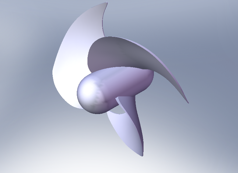
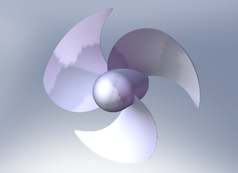
LOW NOISE AXIAL FAN
(A thesis by Selahattin Doğramacı)
( *Click image for video) The following figures show the results after 100 hundred iterations and a full turn of the fan.
Cross-section in z-plane
a) Velocity Vector b) Pressure Contours
As can be seen on Figure (a), the flow is entrained in radial direction and a vortex occurs behind each blade near the connection of hub. Moreover, Figure (b) shows that blades are exposed to counteracting positive static pressure.
c) Pressure Contours with Streamlines ( *Click image for video)
d) Closer View of the Pressure Contours
On Figure (d) it is obviously seen that there is negative pressure on the back side of the blade. Moreover, the lowest pressure occurs at the connection of the back side of the blade and the hub, and there is a uniform pressure distribution on the blade which can be concluded that there is no stall on the blade.
e) Velocity Magnitude f) z-velocity and Streamlines
Figure (e) shows the velocity magnitude distribution x plane at x=0. Fluid particles get faster on their way from inlet region to blades and they have their maximum velocities around the blades. Moreover, after leaving the blades, they slow down as they go to the outlet region. In Figure (f), z component of velocity of the fluid particles are displayed. It can be concluded from the figure that as fluid enters blades, particles are scattered towards the wall due to the centrifugal force. Moreover, because of this centrifugal effect, they become faster and faster as they get closer to the wall. Pressure Distribution on Blades
g) Blowing Side h) Suction Side
Figures (g) and (h) shows the pressure distribution on the front and back surfaces of blades. As can be seen on the figures, on the front side, pressure is rising from hub to the tips of the blades, while there is negative pressure on the back side of the blade surfaces.
|
|
|
|
|
|
Copyright © 2006 ITU School of Mechanical Engineering Fluids Group. | Webmaster| |
.jpg)
.jpg)
.jpg)
.jpg)
.jpg)
.jpg)
.jpg)
.jpg)
.jpg)
%20(372%20x%20330).jpg)
%20(372%20x%20330).jpg)
%20(384%20x%20242).jpg)
%20(376%20x%20234).jpg)